Optimal Wireless Connectivity Improves Performance in Smart Metering

In smart metering systems, RF performance is typically limited by the antenna and its integration rather than the transceiver. Under constrained transmit power and challenging installation environments, antenna efficiency, matching, and detuning directly determine link margin and system reliability.
This article breaks down how antenna losses directly impact the link budget and what realistic efficiency and matching targets look like in practice. It explores how detuning from enclosures, nearby objects, and installation environments shifts resonance and degrades performance, often in ways that are underestimated during design. Frequency dependent constraints are also considered.
On the implementation side, the article looks at PCB integration challenges ground planes, layout and coupling effects that can make or break antenna performance in compact designs. Finally, it connects these RF effects showing how poor antenna performance drives higher power consumption and reduces battery life.
1. Link Budget Impact of Antenna Losses
Typical transmit power levels:
Sub-GHz ISM: +10 to +20 dBm
NB-IoT / LTE-M: +20 to +23 dBm
Antenna-related losses include:
- Radiation inefficiency
- Impedance mismatch loss (S11)
- Detuning in final enclosure
- Range impact (environment-dependent)
Even if range only drops slightly, devices at the edge are already close to the limit. A few dB of antenna loss can be enough to break the link, leading to a noticeable drop in coverage reliability.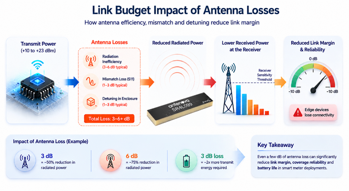
2. Practical Efficiency and Matching Targets
For embedded smart meter designs:
Radiation efficiency
Sub-GHz:
40-60% typical target
Cellular multi-band:
30-50% in compact designs
Matching Target:
- S11 < −5 dB across operating band
- S11: −6 dB = ~25% reflected power
- S11: −10 dB = ~10% reflected power
Mismatch loss directly reduces radiated power and receiver sensitivity.
3. Detuning and Installation Effects
Smart meter environments introduce predictable degradation:
- Metal enclosures
- Internal components (battery, LCD, PCB stack-up)
- Near-field coupling
- Orientation and pattern distortion
This becomes particularly challenging in compact utility meters where batteries, LCD, shielding and nearby PCB circuitry can shift antenna resonance. Antenova’s Gatun embedded antenna is designed for Sub-GHz ISM and LPWAN applications such as 868/915MHz smart metering, where enclosure effects and PCB integration can significantly influence final RF performance and communication range.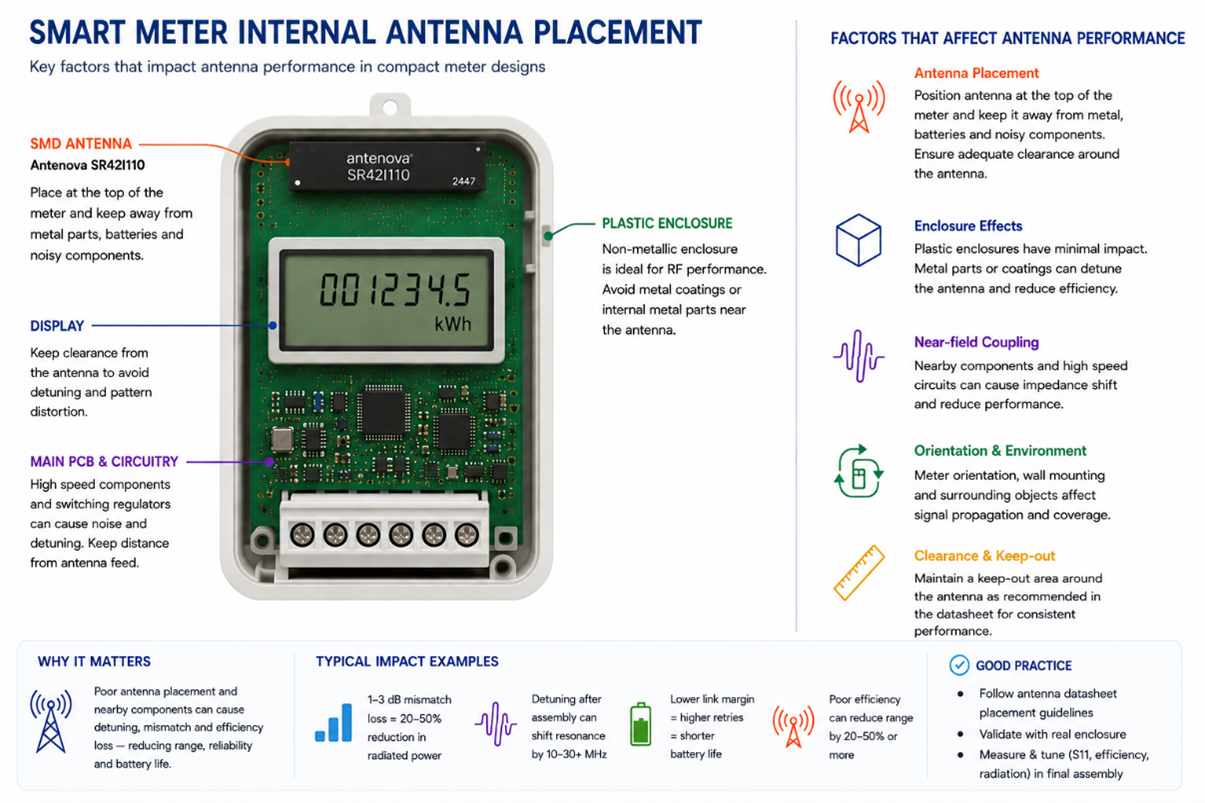
4. Frequency-Dependent Constraints
Sub-GHz (e.g. 868 / 915 MHz)
λ/4 ≈ 82-86 mm
Narrow bandwidth = highly sensitive to detuning
Cellular (698-2100 MHz)
Multi-band operation = wider bandwidth
Matching network complexity increases
λ/4 ≈ 107 mm
Flexible cellular antennas such as Antenova’s Affini 5G antenna are designed for embedded wideband IoT applications covering LTE, NB-IOT and 5G frequency bands. In compact smart meter designs operating across cellular frequencies from 617MHz to 2690MHz, flexible antennas provide additional mechanical integration advantages by allowing placement away from noisy PCB regions and closer to optimal enclosure locations, helping reduce detuning and improve overall RF efficiency.
5. PCB Integration
Antenna behaviour is largely defined by PCB implementation:
Clearance: typically ≥10-15 mm around antenna region
Ground plane size(λ/4) sets resonance (especially below 1GHz)
Matching network (π network) required for tuning
Without proper tuning in the final enclosure:
Resonance frequency shift: 1 to 50MHz
Efficiency variation: 3 to 6dB across builds
For cellular smart meter designs using LTE-M and NB-IOT connectivity, PCB integrations become more complex because the antenna must support multiple cellular frequency bands within a limited PCB area. Antenova’s Inpai embedded cellular antenna is designed for compact IoT devices operating across global cellular frequencies, helping support applications where grounding, antenna clearance, and enclosure tuning directly affect efficiency and overall system reliability.
6. Impact on Power Consumption
Antenna inefficiency increases energy usage through:
- Higher required transmit power
- Increased retransmissions
- Reduced link margin in LPWAN
3 dB antenna loss = ~2× transmit energy required for same link margin.
This can significantly impact systems targeting 10-15 year battery life.
7. Key Takeaway
In smart meter design, antenna performance is a primary contributor to system link budget.
3-6 dB variation in antenna performance is common.
This directly affects:
- coverage reliability
- battery lifetime
- deployment success rate
In practice, this means antenna selection, placement, and tuning should be considered early in the design, not left as a final step.
In the next articles, we will look at antenna design for specific smart meter types, including electricity, gas, and water meters. Each of these comes with different RF challenges depending on the enclosure, environment, and size constraints, which directly affect antenna performance. We will go into practical design considerations and real-world effects for each case.
Talk to Our Antenna Experts
Visit our Product Detail Pages where you will find datasheet, footprint, and 3D models. In addition, you can request a sample and a quote, check distributor availability, and try out the Antenna Placement Tool.
Need support with antenna integration or looking for a custom solution? Our engineering teams are ready to help with design, optimisation, testing, and sample selection for your wireless project. Let´s talk about your request.
or Join our global antennas & wireless design community at ask.antenova forum. This is an opportunity to communicate directly with our top engineers as well as community members.
View related articles:
How to enhance and guarantee the range of smart meter applications
Maximising the wireless performance of smart meters: overcoming signal attenuation challenges
Can signal shielding enhance smart meter connectivity?
4 ways to increase wireless antenna performance in metal devices