Where to place your antenna for optimum performance
.
Antenna placement
As circuit boards get smaller and more compact, finding sufficient space for an antenna becomes more of a challenge. Even when antennas are already placed, the first place many designers look to reduce space is in the antenna’s ground plane.
At sub-GHz frequencies, a reduction in ground plane can make a huge difference to performance. Even a small drop in plane size can reduce efficiency dramatically. For devices which need to meet certain thresholds to achieve certification, this is a key factor.
Why is antenna placement so important?
Unlike other sorts of integrated circuits, antennas must abide by the laws of physics in order to function. Every antenna has a unique radiation pattern, which, among other factors, will determine where the optimum position of an antenna will be on a circuit board. Generally, the best place to position an antenna is along the long-side edge of a circuit board. Data sheets will outline placement recommendations for each antenna.
Embedded antennas: the key considerations
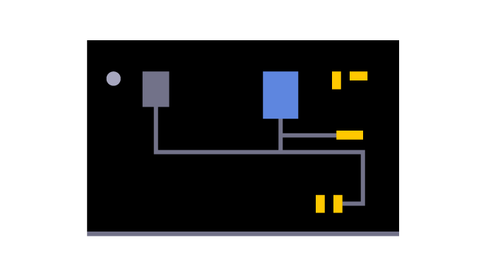
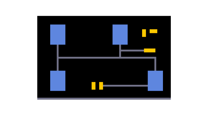
Ground plane size
Ground size is an important factor when using an embedded antenna. The ground plane constitutes a crucial part of the antenna. This makes following the recommendations outlined in the datasheet imperative for performance. If ground plane space is an issue, then consider integrating an FPC or case-mounted antenna.

Antenna selection & placement tool
Find the right antenna for your project based on your wireless requirements and PCB size.

Best practice for antenna placement
Clearance
Antennas require clearance across all layers to operate well. Clearance requirements vary with each antenna. This makes it essential to review antenna datasheets carefully before selecting one.
Position
The radiation pattern of every antenna is unique. For this reason, antennas have recommended placement instructions detailed within datasheets. For some, the optimum location is on a PCB corner, for others, it may be the long-side edge.
Antenna feed
Feed tracks are another important consideration while integrating an antenna. The grounded coplanar waveguide model is particularly useful in small designs. However, they should be kept short and not contain 90 degree corners, as to minimise losses.
Matching network
Embedded antennas will require a matching circuit to operate effectively. 3-component Pi matching circuits offer a means of achieving a close match while minimising the footprint of RF circuitry within a design.
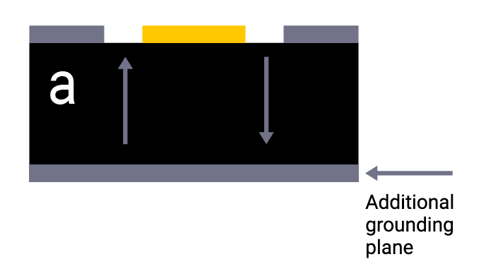
PCB stackup
There are a whole host of advantages to using four plus layer circuit boards. Knitting these layers together provides better isolation and creates an environment conducive to RF performance. Use evenly spaced vias to knit these layers together, this helps prevent ground loops/paths. Antenna integration can become more of a challenge on smaller PCBs, particularly at sub-1GHz frequencies.
Device application
Products used in the hand or worn bring an additional set of considerations to antenna placement. Leaving a sufficient gap between the antenna and the product housing can help counteract the detuning effects caused by users. Additionally, antennas can be matched to work more efficiently while being held or worn.
Mission impossible? How well can an embedded antenna perform on a tiny PCB?
Download our whitepaper to learn how can designers ensure a device performs well with a small circuit board and minimal power consumption.
Transmission line calculator
Get quick, easy and flexible options when selecting the optimum dimensions of your transmission lines.

Antenna placement resources


ask.antenova
ask.antenova is a global forum for designers and engineers working with wireless technology. Get answers from those who know best.